

Using a Flipper Zero to access API source code on IoT devices
So you want to hack an API running on an IoT device. I don’t blame ya. Exploiting a web app or API on an IoT device is a lot of fun these days. So many useful tools can help to make it much easier for you.
In today’s article, I will show you how you can use a Flipper Zero to interface with an IoT device and gain access to the source code of the web app and API that run it. In my case, I am going to beat up on one of my popular wireless hacking rigs, an old Hak5 Wifi Pineapple.

Let’s get right to it!
Gutting the Wifi Pineapple
So this old Pineapple I have is a Mark IV, based on the Alfa AP121U. To get to the guts of the device, we need to remove the two feet from the bottom (farthest from the antenna adapter and closest to the USB port) and then remove the two screws hidden behind them. The top should then be able to come right off.

With the cover removed, we can start to recon the hardware board and look for interfaces we can tap into.
Finding and mapping the UART interface
When we look closely, we can see four pins tied together on the right side, closest to the USB port. This is a good candidate for being a Universal Asynchronous Receiver/Transmitter (UART), a serial communication interface that can, in some cases, get us access to the serial console when the device is running.
As the PINs aren’t marked, we need to verify if this is a UART by hand. What we want to do is figure out the following about the four pins:
- Which pin is ground (GND)
- Which pin is power (VCC)
- Which pin is receive (RX)
- Which pin is transmit (TX)
Finding the ground pin
To detect which pin is GND, we can use a digital multimeter.
Using my pocket Fluke, I switch it to “continuity” mode, which shows as an ohm sign, and then press the yellow button to activate the continuity test signal. If you touch the two leads together, the multimeter should beep.
Place the black lead somewhere on the circuit board that appears to be grounded. I decided to use the metal ring around one of the screw holes. Now place the red lead on each pin, one by one, until you hear a beep. That is your ground pin.
In my case, it was the fourth pin, closest to the outside of the circuit board.

Finding the power pin
The next pin we want to detect is the power pin. This is more commonly called VCC. For most circuit boards, this will either be 3.3V or 5V.
To measure this, we will need to apply power to the device and check the remaining three pins looking for a steady voltage across the pin. My Pineapple can be powered from a battery pack called a Pineapple Juice. Plugging that in and powering it on will immediately start the process.
Using the multimeter again, but set to measure voltage, we again place the black lead to GND and then look through each pin as the device boots up. We can quickly see that the VCC pin is the first pin farthest from GND.

Finding the receive and transmit pins
With the device still powering up, I move to check the two remaining pins. One pin, closest to VCC, doesn’t have any voltage to it. But the pin nearest to GND fluctuates between 1 and 2.5V. That’s a clear signal that the device is sending something down that pin. If you think about it, when a device boots up, it sends lots of text to the console; that is what we are seeing here.

Now that we know what the four pins do, we can figure out how to wire them up to the GPIO pins on the Flipper Zero.
Wiring up the Flipper Zero to the Wifi Pineapple
On the top of every Flipper Zero is a series of holes representing the GPIO pins. The pin layout looks like this:
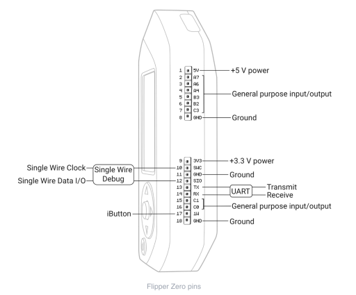
We can see from the diagram that the Flipper Zero has UART Transmit (TX) and Receive (RX) pins. We have to realize that something transmitting (TX) from the Pineapple is actually receiving (RX) on the Flipper Zero. So we have to swap the TX and RX as we hook everything up.
To wire up the Pineapple to the Flipper Zero, we need to set it up as follows:
- We don’t wire up VCC. We leave that pin alone on both devices.
- We wire up the GND of the Wifi Pineapple to pin 11 or pin 18 of the Flipper Zero.
- We wire up the RX of the Wifi Pineapple to the TX of the Flipper Zero, which is pin 13.
- We wire up the TX of the Wifi Pineapple to the RX of the Flipper Zero, which is pin 14.
In the end, it will look something like this:


Intercepting the serial signal over UART
Now that we have all the hardware setup, it’s time to turn to the software.
First, plug in your Flipper Zero to a USB port on your computer.
Now on the Flipper Zero, go to the GPIO menu and select it. And then from there, select the USB-UART Bridge.

Back on your computer, you will now need to interface with your Flipper Zero over a TTY. If this is Windows, it will probably be a COM port. On Linux, it will typically be /dev/ttyACM0. On a Mac, it will typically be /dev/tty.usbmodemflip_<devicename>1.
Whatever the TTY is, you will need to connect to it. On Windows, you can use a terminal emulator like Putty. On Linux and Mac, you can use something like minicom or screen.
I’ll use screen. I need first to determine what TTY my Flipper is connected to:
$ ls -lart /dev/*flip*
crw-rw-rw- 1 root wheel 0x9000002 14 Jan 16:05 /dev/tty.usbmodemflip_Eolam1
crw-rw-rw- 1 root wheel 0x9000003 14 Jan 16:05 /dev/cu.usbmodemflip_Eolam1
Now I can connect to it using the screen:
$ sudo screen /dev/tty.usbmodemflip_eolam1 115200Power up the Wifi Pineapple. If everything has been set up correctly, you will start seeing the IoT device post messages to the console screen.
Finding the API source
At this point, every IoT device will differ. There is a good chance that if you hit return, you will get dropped into a terminal. In my case, the Wifi Pineapple drops me directly into a root shell without the need for a password.
From here, you start your file system and process recon; you are looking for which processes are exposing network ports you can connect to and where those processes are accessing files within the device. There, your API artifacts will probably reside.
The API artifacts may not be in a source format. Many IoT devices might actually have small, tight binaries that you will have to exfiltrate and then reverse engineer with tools like Ghidra, IDA, or Binary Ninja. Others may be running byte code in Java or .NET, which you will have to decompile. I have written how to decompile Java APIs before. And here is another one on how I reverse engineer .NET APIs.
In my case, on this version of Wifi Pineapple, it’s pure PHP. So by exfiltrating the pineapple directory within the www directory, I can extract all the code I need from it.

YMMV, of course. At this point though, you are using the Flipper Zero to bridge into a serial console of your IoT device. The device is yours to pwn.
Conclusion
As you can see, using a Flipper Zero to bridge into an IoT device’s serial console is a powerful and useful tool. It allows you to gain access to the source code of the API without having to resort to either expensive JTAG or chip extraction tools. With this method, you can quickly get to the root of any vulnerable APIs running on your target device!
Happy hacking!
Like to learn more interesting things about hacking APIs? Make sure you check out my free ebook on The Ultimate Guide to API Hacking Resources.
The post Using a Flipper Zero to access API source code on IoT devices appeared first on Dana Epp's Blog.
*** This is a Security Bloggers Network syndicated blog from Dana Epp's Blog authored by Dana Epp. Read the original post at: https://danaepp.com/using-a-flipper-zero-to-access-api-source-code-on-iot-devices
